This section covers the design and build of the parallel port. It includes general details on the required ROM interfacing to the GameBoyTM The GB-Adapter is a cartridge supporting the addition of 32k*8 and 64k*8 EPROMs.
[ Only the term EPROM will be used. PROMs EPROMs OTP-EPROMs having the same pinout may also be used. Flashs and EEPROMs have nearly the same pinout whereby they require a different programming method]
The capability of the
standard programmable I/O chip 82C55A will be considered and the
GB-I/O parallel port project circuit diagram described. A
ready-to-etch layout for the printed circuit board is included as
part of the design.
The very first step in developing software for the GameboyTM is to connect the required program memory to the 'Gamepack Edge Connector' (GEC). This can be done in different ways. One possibility is to take an old cartridge (maybe with an MBC1), solder the ROM out and connect all of the data and address to an EPROM.
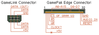
Figure 7: GameLink- and GamePak-connector pinout
On the right of Figure 7 is a view of a cartridge connector as seen from the GameboyTM slot (the text on the cartridge is on the upper side). The picture shows the pinout of the cartridge and should be used for further reference.
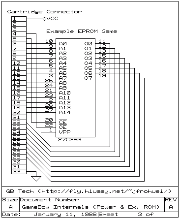
Figure 8: Wiring diagram for an EPROM
 Any CMOS EPROM witch an access time
of less than 150ns.may be used.
Any CMOS EPROM witch an access time
of less than 150ns.may be used.
Figure 8 shows the wiring diagram for an 32k*8 EPROM. Address and data lines are connected directly. The power for the EPROM (Vpp) can be obtained from pin 1 (Vcc) of the GEC. Ground (GND) is connected to pin 32 (GND) of the GEC.
A bit more tricky are the chip enable (/CE) and output enable (/OE). They are connected to read (/RD) and write (/WR) respectively. Notice for further development that all these signals are low active.
To access the lower or upper half
of a 64k*8 EPROM simply use a jumper or switch to connect A15 of the
EPROM either with GND or Vcc.
The GB-Adapter is a
simple adapter from the 'Gamepak Edge Connector' (GEC) to a 28 pin
DIP socket. It supports 256Mbit and 512Mbit EPROMs. When using a
512Mbit (64k*8) EPROM J3 is used for selecting the upper or lower 32k
of the EPROM.
All
32 pins of the GEC are also available on a standard 2x17-pin
connector on the adapter board. The idea of the adapter was to create
an easy way to connect further circuitry to the GameboyTM.
An EPROM can also be mounted on the board if required. The capacitor
provides for ripple and spike supression and should have a value of
around 100nF (C1).
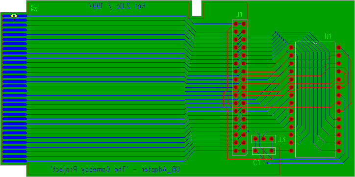
Figure 9: Board layout for the GB-Adapter
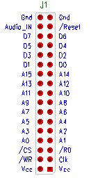 Figure 9 shows the
board layout. To download the
ready to etch layout plans simply click on the image. Note that the
view is from the component side of the board through to the solder
side.
Figure 9 shows the
board layout. To download the
ready to etch layout plans simply click on the image. Note that the
view is from the component side of the board through to the solder
side.
The
connector J2 may be used as an expansion slot for further
applications.
Pin
1 & 2 of J1 (=J1.1 & J1.2) are connected to pin 1 of the GEC
(= J2.1). Pin J1.3 goes to J2.2, J1.4 to J2.3 and so on (See figure
10 on the left). The /WR of the GEC is not routed to the EPROM
but to A15 to disconnect the EPROM from the data bus while not in
use.
![]()
![]()
![]() This document was created with StarOffice
4.0 by Marc
Rawer
This document was created with StarOffice
4.0 by Marc
Rawer